The digital I/O pin
The Arduino Uno can supply a digital output signal on its 14 digital input/output (I/O) pins. In most instances, the pins used to provide these signals are pins 2 through 12. Pins 0 and 1 are also used by the Uno to effect serial communication and it is good practice to not use these pins in a project unless absolutely necessary. The output of Pin 13 is connected to an on-board LED and a current limiting resistor - this pin is usually held in reserve for debugging purposes and again it is good practice to not use this pin in a project unless absolutely necessary.The digital I/O pins 3, 5, 6, 9, 10 and 11 can be used as I/O pins but can also provide PWM output using the analogWrite() function.
The digital I/O pins 2, 4, 7, 8, 12 can be considered the most basic type of digital pin. In the most generic sense, digital I/O pins can be thought of as the output of a switch that can can be toggled between two terminals where one of the terminals is held at positive five volts (+5V) and zero volts, also referred to as ground (GND). This digital "switch" is then controlled via software, which is to say, the pin does what the program (or sketch in Arduino speak) tells it what to do. This concept of the digital pin as a switch is shown in the figure below.

The digital pins on the Arduino can be used in two modes: they can provide a digital signal - this is the OUTPUT mode, or they can be used to receive a digital signal, this is the INPUT mode. In order to use a pin, the mode of operation must be specified in the sketch - typically this is done within the setup( ) function using the defined function called pinMode( ).
As an example, the following line of code sets the digital I/O pin number 3 to OUTPUT mode.
pinMode( 3, OUTPUT);
Once the mode is set to OUTPUT, the boolean value of the digital pin can be set using the predefined function digitalWrite( ). The pin value can be set to HIGH (+5V) or LOW (GND). The following are examples of the code usage and the figures show the resulting "physical" process. Again, pin 3 is used.
digitalWrite( 3, HIGH);

digitalWrite( 3, LOW);

Using digital output
Digital pins are typically used in two ways. The first is to send digital information to another device and the second is to act as a combination power source and switch to a limited set of components such as LEDs.Sending digital information
The Arduino is often used to control different types of motors. This is commonly done through the use of a motor control board such as the Pololu Qik 2s9v1 Dual Serial Motor Controller or the EasyDriver Stepper Motor Driver. In a typical arrangement a number of the Arduino digital I/O pins are use to send signals to the motor driver boards. The signal requirements are different for each board and are commonly controlled via libraries that are meant to be used with the boards. Nonetheless, the Arduino sketch will use the digitalWrite function with the HIGH and LOW modes to provide the required digital signal to the board. This concept is shown in the following figure.
Controlling components
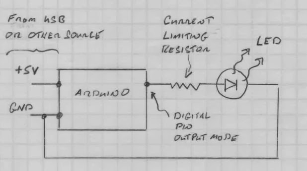
The second use for the digital pins is to provide current to operate a component such as an LED. When used in this manner, the Arduino documentation states that no pin should be allowed to source more than 40 mA of current and the recommended steady current is around 20 mA.There is also a specified upper limit of 200 mA for the entire Arduino board. Thus one must be very careful when using the Arduino to provide operating current to more than a few simple components. For instance - using the Arduino to control 10 LEDs can easily exceed the 200 mA limit of the board.When using components that draw current it is important to calculate the possible current drawn and use an in series resistor to limit the maximum current draw - this is sometimes referred to as a current limiting resistor. The typical setup for using a digital output pin to control an LED is shown in the figure below. Note that the figure explicitly shows that the Arduino requires power from an outside source which can either be a USB cable connected to a PC or some other DC power source (7-15 V) that is connected to the Arduino input power jack. The ground line of the power source is connected to the Arduino and the figure notes that this is the same ground that is used by the LED circuit.
Code example
The following complete code is an example of the use of digital output. Digital pin 3 is given a descriptive name "redLedPin", its mode is set to output and its state is toggled from high to low repeatedly in a loop. A video of the circuit setup and running is provided below the sketchSketch
Video